

Did you know that ground fault protection has been required on service entrance switchgear since 1971? Despite being required under the National Electric Code (NEC/NFPA-70) in Sections 230.95, 215.10, 240.13, and others, in most electrical distribution systems, many people are uninformed about how the protection process actually works.
Recently, a client reached out because they experienced a situation where their ground fault protection system caused the service main to trip. A lighting ballast was being replaced, and an electrician accidentally caused an arc. The ground fault protection system detected the fault and tripped the main breaker, which is precisely what it is designed to do in such a scenario. This is a common situation we encounter in our industry, where many of our clients are unaware that their ground fault protection system has successfully done its job, especially when it comes to faults in lower current circuits.
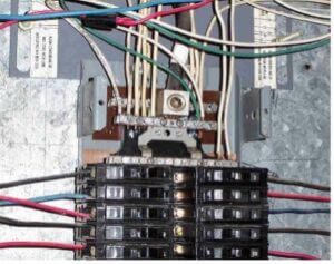
Ground Fault Protection and Your Circuit Breaker Panel
In a circuit breaker panel like the one shown to the left, the circuit conductors are connected to the circuit breakers, and their respective neutrals (the white wires) are connected to the neutral bus and aren’t connected to the breaker. These wires are the return path for the current in the circuit. Single phase breakers like the ones shown here are often thermal-magnetic, meaning they operate based on the amount of current through them to protect the circuits they feed from an overload condition.
If the current through the phase conductor (the wire coming off the breaker) exceeds the breaker rating, the resultant increase in heat will cause the breaker to trip. A ground fault on a circuit being fed from a single-phase breaker like those shown wouldn’t necessarily cause that issue.
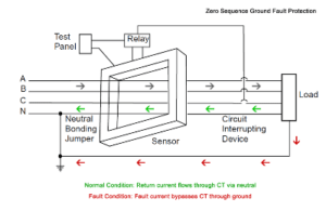 Ground fault protection is a vital personnel protection measure. It helps decrease the risk of electrical shock to people performing energized work by clearing a fault much more quickly than typical overload protection would. It often clears a much larger breaker upstream from the fault because that’s where the ground fault protection is installed. The diagram to the right depicts a zero-sequence ground fault protection system. In this type of configuration, there’s a single current transformer (CT) monitoring the phase conductors, measuring the current level through them.
In a balanced three-phase system, the current levels are equal, and the vector sum of the currents is zero, so the relay protecting the system doesn’t detect a fault. When a ground fault occurs, the vector sum is no longer equal to zero because the fault current causes a magnetic flux in the toroidal core of the CT. This activity induces a voltage in the CT’s secondary, which activates the ground fault relay. The relay trips the protective device (like the service main), disconnecting the system to protect the facility.
This functionality could become a nuisance if a facility has abundant ground fault conditions with any kind of regularity. If that’s the case, installing ground fault protection at essential points in the electrical distribution system that are downstream from the main is a great alternative to ensure the protection of your electrical systems.
If you have questions about your ground fault protection or anything else, contact us >